
The aGmX Embedded Static Nano PMS module Series are designed to ensure the lowest possible and quietest possible output ripple noise, and the highest possible stability of the power supply system, as well as the output stability, and the output availability, and to achieve the highest possible efficiency. The Nano PMS module also attempts to achieve the highest possible level of other power supply parameters, such as Load Response, Line Response, etc.
The goal of The Nano PMS module also includes providing an very stable and very low noise level power supply for the back-end system and all while taking efficiency into account (very beneficial for the RF system that use this Nano PMS module as the system front-end power supply).
The main design features of the aGmX05302ASL module are wide voltage input, high adaptability, mainly for the conversion of new energy power supply as input, due to the large voltage range and transient changes.
It has the functions of transient surge absorption suppression at the both input and output terminal, output over-current protection, output short-circuit protection, over-temperature protection and self-recovery.
NOTE: All tests were performed at a room temperature of approximately 19°C .
The image below shows the temperature distribution of the aGmX05302ASL after stabilization under medium load, and the maximum temperature can be observed to be only 34°C (this is a basic reliable temperature, since the surface to be measured is a matte non-metallic surface). The minimum temperature is 17.9 °C, this is because there are bare test points on the module PCB for testing, and the test clamp is also made of glossy metal, because the infrared emissivity of glossy metal is lower than that of other non-metallic surfaces, so when the default emissivity of the thermal imaging device is set to a high emissivity material, the observation temperature of the glossy metal will be lower than the actual material temperature, that is, the inaccurate minimum temperature below the test room temperature(19°C) as seen on the thermal imaging picture (so we do not use it as a reference).
.jpeg)
Medium load(Thermal Imager 2022)
.jpeg)
Typical load(Thermal Imager 2022)
.jpeg)
Near maximum limit load(Thermal Imager 2022)
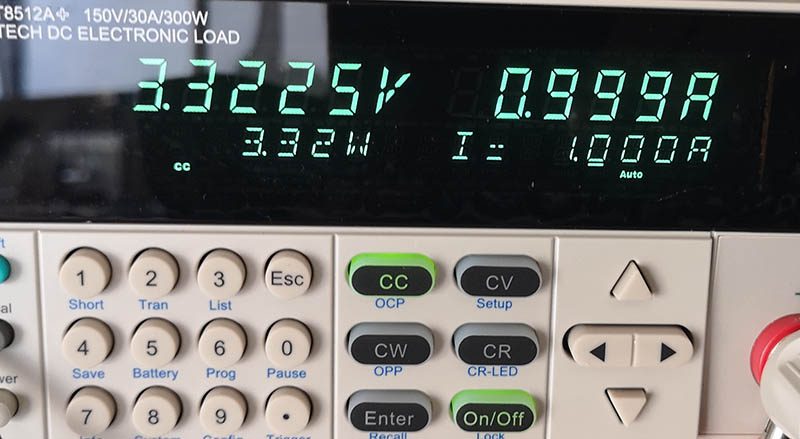
Typical load (Precision load meter 2022)